![]() In case you haven’t heard, we released CityEngine 2017.1 two weeks ago! We are super excited about the new features, which you can catch up on in this blog post. Today, however, we’re going to dive deep into the new Visibility Tools! The latest version of CityEngine supports several types of Visibility Analysis directly in your 3D scene. This is an interactive analysis, allowing you to play around with different viewshed scenarios and see the impact on the surrounding area in near real-time. The Visibility Analysis tools display surfaces and structures that are visible and hidden from an observer, allowing you to get a comprehensive view of your scene & the different scenarios within your scene. You can perform visibility analyses of static and dynamic models, streets, and terrain. All Visibility Analysis tools are scene objects that are saved in the scene, allowing you to edit layer details, such as distance, location, and symbology.
In case you haven’t heard, we released CityEngine 2017.1 two weeks ago! We are super excited about the new features, which you can catch up on in this blog post. Today, however, we’re going to dive deep into the new Visibility Tools! The latest version of CityEngine supports several types of Visibility Analysis directly in your 3D scene. This is an interactive analysis, allowing you to play around with different viewshed scenarios and see the impact on the surrounding area in near real-time. The Visibility Analysis tools display surfaces and structures that are visible and hidden from an observer, allowing you to get a comprehensive view of your scene & the different scenarios within your scene. You can perform visibility analyses of static and dynamic models, streets, and terrain. All Visibility Analysis tools are scene objects that are saved in the scene, allowing you to edit layer details, such as distance, location, and symbology.
There are three new Visibility Analysis tools in CityEngine 2017.1: the Viewshed tool, the View Dome tool, and the View Corridor tool. This blog aims to review each tool, the use cases surrounding the tool, and go through the steps to get started with the tool. For a deeper dive into these tools, please visit the online reference help.
Pssssst – learn more about CityEngine 2017.1 in the 2017.1 release notes. And if you haven’t already, go to My Esri to upgrade to CityEngine 2017.1. Or, if you are new to CityEngine, try it now with a fully functional free trial version.
Viewshed Creation Tool
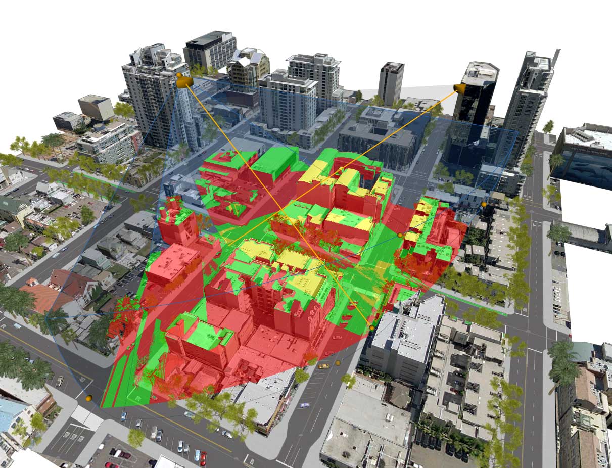
The Viewshed Creation tool shows visibility from a camera-like observer to a specified target. This allows you to identify visible and non-visible objects in a specified extent. The Viewshed Creation tool can be useful in assessing a view from an existing apartment to a new building site, identifying views to key points of interest, or identifying camera coverage for security purposes. Being able to identify visible and non-visible areas with just a few clicks enables you to quickly iterate on multiple scenarios that best suit your city’s building specifications or security requirements, and understand the impact on the surrounding area.
To create a Viewshed in your CityEngine scene, follow these quick steps:
- With a scene open, click on the Viewshed Creation tool on the top ribbon.

- Next, you’ll drop two points into the scene. The first point you drop will be the observer feature, or what point the viewshed will be created from. Click to start the viewshed tool and a line dynamically displays the Viewshed as you move it to set target, or the second point.
- After clicking on both of those points, your viewshed is created! You can edit the viewshed by clicking on either the observer or target points and moving them.
- Everything in green is what can be seen by the observer; everything in red represents what is within the viewshed extent, but not visible from the observer’s vantage point.
Note: you can create multiple viewsheds, and see how they interact with each other. Where the viewsheds overlap, the color will be yellow.
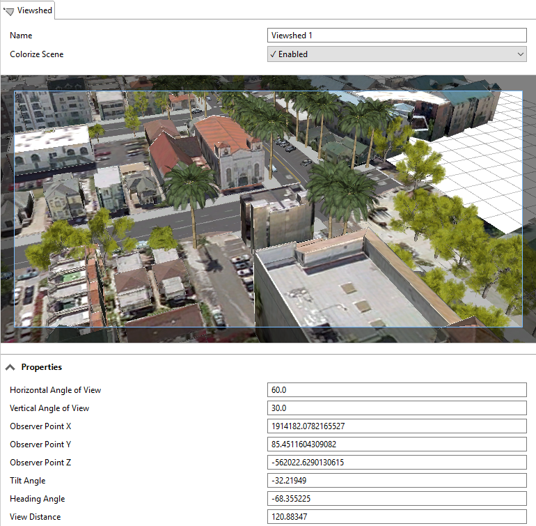
You can also edit your viewshed in the Inspector window. After you drop the two points to create the viewshed, you’ll see the object is added to the Scene editor. By clicking on the object in the Scene editor, the layer will become active in the Inspector. The Colorize Scene property allows you to choose whether you want to display the colorized visible or hidden areas in the 3D viewport. The preview shows the view from the observer point, enabling a more comprehensive understanding of the viewshed. You can also manually edit the View Distance, location, and angle of the viewshed in the properties section.
View Dome Tool
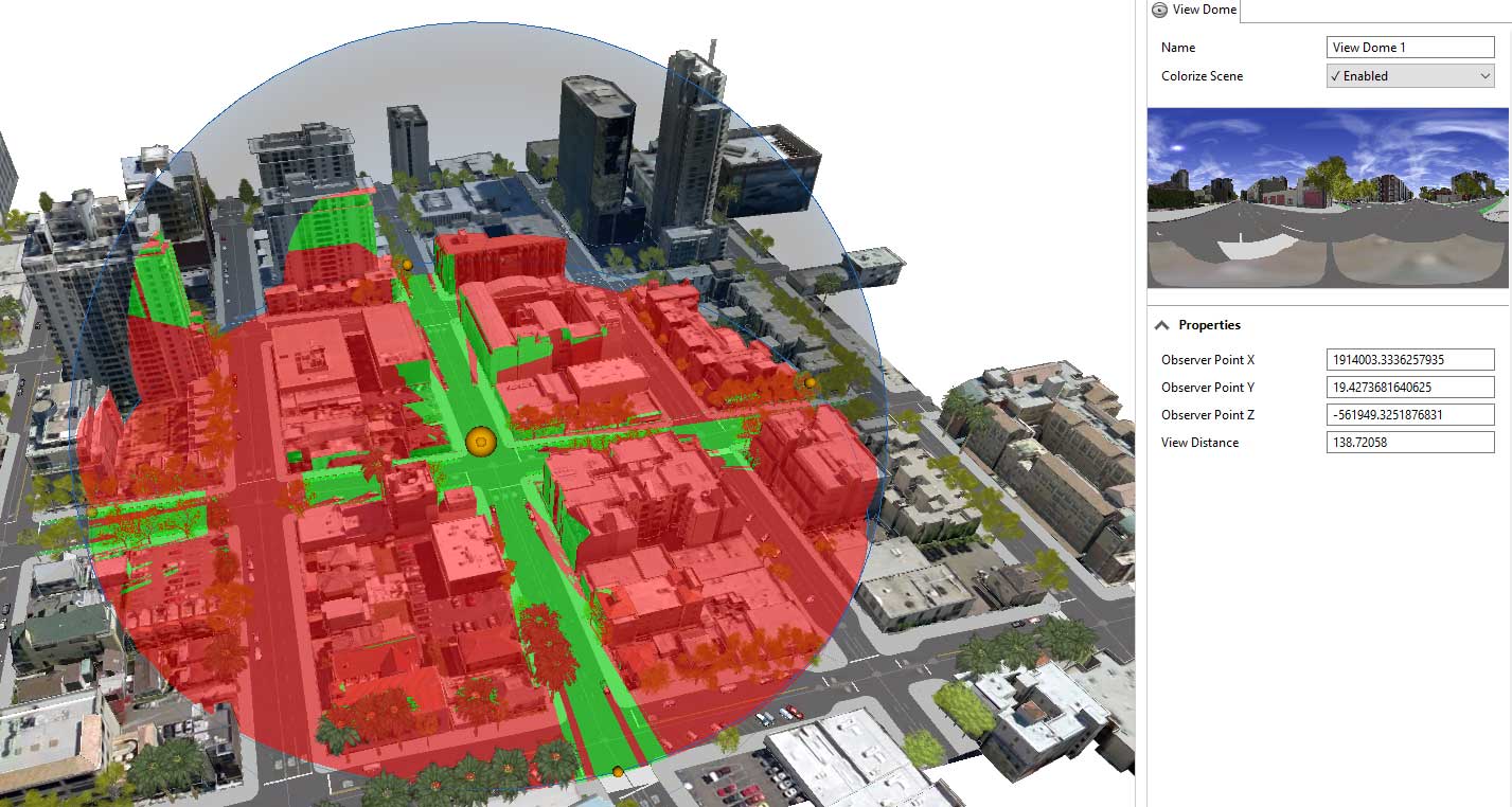
The View Dome tool gives you 360-degree visibility from a single spot, and can work with multiple points to show where visibility coverage overlaps. Both the Viewshed and the View Dome tools are designed to easily allow you to identify visible and non-visible areas of your 3D model from one or multiple observer points. You can quick edit the observer point, point of interest, and the field of view in the 3D viewport using handles that become interactive when the scene object is selected. Manual control over these parameters is available in the Inspector, similar to the Viewshed Creation tool.
![]() To create a View Dome, activate the tool on the top left ribbon in CityEngine, and click on anywhere in the scene to set the observer point. Once the point is set, you drag to create the View Dome. Once created, the View Dome is automatically selected, and you can directly adjust its properties, such as the view distance in the Viewport using handles or in the Inspector using input fields.
To create a View Dome, activate the tool on the top left ribbon in CityEngine, and click on anywhere in the scene to set the observer point. Once the point is set, you drag to create the View Dome. Once created, the View Dome is automatically selected, and you can directly adjust its properties, such as the view distance in the Viewport using handles or in the Inspector using input fields.
View Corridor Tool
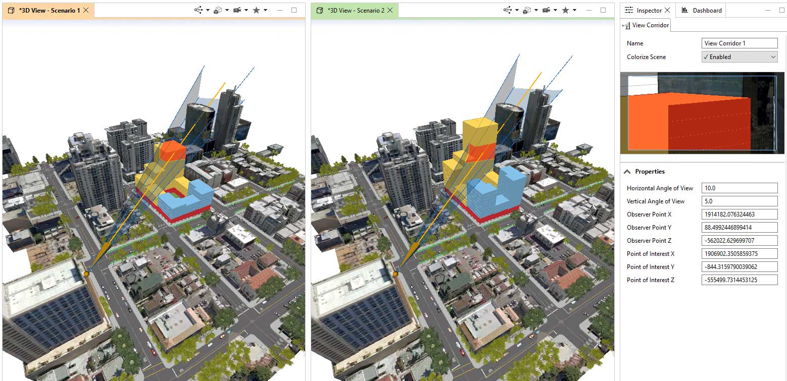
The View Corridor tool can be used to determine which buildings interfere with a view corridor. View Corridors protect established views from a given observer against building development obstruction. To support this use case, the tool creates a protected view where any scenario building visible in the corridor is colored. This makes it easy for you to design your proposals to fit optimally into your city model, without disrupting the View Corridor.
Note: View corridors are designed to analyze scenarios. It is recommended to create scenarios first before creating the view corridor objects because only buildings in a scenario are colorized by the View Corridor.
To create a View Corridor, follow these simple steps: ![]()
- Activate the tool in the top left ribbon in CityEngine.
- Click a point in the viewport to create an observer point. This starts the View Corridor tool and a line dynamically displays the View Corridor as you move it to set the point of interest.
- Click again to anchor the point of interest in the View Corridor.
Once created, the View Corridor is automatically selected, and you can directly adjust its properties, such as the angles of view in the Viewport using handles or in the Inspector using input fields.
Tip: Not loving the colors of the Visibility Tools? No worries – the symbology for each tool can be changed in the Inspector. The default colors are: green (visible), yellow (visible by multiple viewsheds/domes), and red (not visible by any). To change the colors of the Analyses, click on the Analyses Layer in the Scene window. The Inspector will automatically open the layer details, where you can edit the name of the layer, visibility, locked, colored, and the layer color.
To see the tools in action, check out this YouTube video!

Article Discussion: