Editing and data compilation are less commonly thought of as operations that can be automated through geoprocessing. However, ArcGIS 10 introduced the Editing toolbox, which contains a set of geoprocessing tools to perform bulk edits. These tools combined with others in the geoprocessing environment can automate data import and maintenance work. Automated data compilation tools are especially useful for importing data into a geodatabase but can also be employed on a regular schedule to perform routine quality assurance (QA) checks. In this entry, I will discuss the use of geoprocessing to clean CAD line data as part of the import process.
Importing data with geoprocessing
Lines that are created without the use of spatial integrity measures, such as snapping or topology, almost always contain some inconsistencies. These errors are likely in data that originated in formats such as CAD, shapefile, or KML. Fortunately, many common topological issues can be resolved in an automated manner by using ModelBuilder to link together tools that will import data into a geodatabase and perform standard data cleanup techniques.
I have a CAD file for a new subdivision that needs to be integrated with my existing GIS parcel data. The GIS data must be kept to stringent accuracy standards, so I need to fix any issues where lines do not connect to each other, overlap, or are duplicated. Rather than risk reducing the quality of the main parcels geodatabase, I can create a local temporary geodatabase where I can preprocess the CAD lines before introducing the features into the production geodatabase. Although the CAD file contains buildings, roads, text, registration tic marks, and other features, I plan to use only the parcel lot lines.

I have built a model that imports the CAD lines into a temporary scratch workspace, cleans and processes the lines, and then copies the corrected lines into an output file geodatabase. When importing CAD data into a geodatabase, I can choose from several available tools, including CAD to Geodatabase or Feature Class to Feature Class. The CAD to Geodatabase tool converts all the geometries in a drawing to individual feature classes, such as a line feature class for the parcel lines, annotation feature class for CAD text, and so on. In my case, I am using Feature Class to Feature Class tool because I need only the lot line geometry from the CAD file. This tool makes the model reusable because it can import many different formats and not simply CAD. In addition, the Feature Class to Feature Class tool allows for an SQL expression so I can further refine the import to include only the CAD features that satisfy an attribute query for lot lines (in this case, “Layer” = ‘LOT-L’).
Performing automated quality assurance on lines
Once the CAD parcel lot lines are imported into a geodatabase feature class, I can begin running tools to perform automated QA processes. Many tools are found in the Editing toolbox, although other toolboxes can be purposed for data compilation QA tasks. For example, I can start by using the Integrate tool in the Data Management toolbox to address minor inconsistencies in the line work. Integrate makes features coincident if they fall within the specified x,y tolerance. By using a small tolerance on Integrate (and other similar tools), I can avoid editing the data beyond the level of cleanup I intended. In addition, since I am running the tools on a copy of the data outside my production database, I can run the tools repeatedly to refine tolerance values to fix more issues in an automated manner. The intermediate data created as the model runs is maintained and can be reviewed in the scratch geodatabase.

After the dataset is integrated, I check for duplicated lines with the Delete Identical tool (Data Management toolbox). The dashed lines connecting to this tool represent preconditions, which are used to control the order of operations in a model. For example, the Integrated Lines output is a precondition to the Delete Identical tool. This way, the Delete Identical tool will not execute until the lines have been integrated.
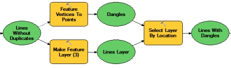
The next part of the model identifies lines that are dangles. With the Feature Vertices to Points tool in the Data Management toolbox, I create a new point feature class containing the line endpoints that are not connected to any other lines. I can then use Select Layer By Location to identify the lines that intersect these dangling endpoints. The resulting selection represents lines with dangles.
Many of these dangle errors can be fixed by running the Editing toolbox’s Trim Line, Extend Line, and Snap tools. Effective use of the Editing toolbox geoprocessing tools can improve productivity because the tools apply edits in bulk, such as to all features or all selected features. In most cases, the similar editing function applies to only one feature at a time. Because I exposed the tolerances as variables and model parameters, I can easily run the model with different values because the tolerance settings appear as input boxes on the tool’s dialog box. For example, I am willing to extend or trim the lines from this CAD dataset initially up to a maximum length of five feet. After that procedure, I want to inspect the lines visually to see how many issues remain to ensure that I will not be making incorrect edits if I increase the tolerance value. I can change the tolerance as needed depending on the accuracy of the lines I am importing.

In addition, since my organization’s spatial integrity rules indicate the parcel lines should be split and not intersect themselves, I can use a sequence of spatial and attribute queries to find the locations where lines have intersecting endpoints. Lines are often split so that each length can be attributed separately.
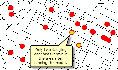
Once these processes have run, the lines are output into a feature dataset in a geodatabase and are much cleaner topologically. After the model completes, I can run the Feature Vertices to Points tool again on the cleaned output to see the remaining dangles and compare the current number of endpoints that are dangles (the yellow circles in the graphic) to the number in the original CAD lines (the red circles). While there may be a few remaining issues, there are less than before running the model. At this point, I can build a geodatabase topology to check for and repair any other errors. When I am satisfied that the lines meet the standards for our spatial data, I can import it into the production database.
For more information:
The sample tools and data can be downloaded from the Editing Labs group on ArcGIS.com. An ArcInfo license in required to run the tools.
Commenting is not enabled for this article.