Command and Control (C2) Tactical Symbols, as specified in Mil-STD-2525C, represent Units, Equipment, or Installations. They present information that can be pinpointed in one location at a particular point in time. These symbols are composed of frames, fills, icons, and text. The size and shape of a symbol are fixed and remain constant, regardless of the scale of the background projection, unless changed by the operator.
Given the requirements of the standard, how do we represent them in ArcGIS? Tactical Symbols are created in ArcGIS as Unit, Equipment, and Installation (UEI) Features. The UEI Features are stored as point features in a geodatabase. UEI Features are drawn with marker symbols, which are composed of one or more symbol layers that show the frames and fills, with additional symbol layers that provide information about each symbol’s identity, battle dimension, status, and mission.
Composition of tactical symbols
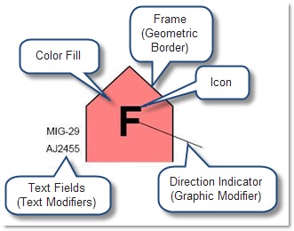
In Mil-STD-2525C terms, a fully displayed tactical symbol is composed of a frame, fill, and icon. It may include text and/or graphic modifiers that provide additional information. The frame attributes (i.e., standard identity, battle dimension, and status) determine the type of frame for a given symbol. Fill color is a redundant indication of the symbol’s standard identity, with red representing enemy and blue representing friendly.
The number of possible combinations of the various Tactical Symbol components is in the millions. Rather than attempting to create a unique symbol for each of these, we’ve stored the components used to draw a UEI Feature as individual marker symbols in style files. These style files are installed with ArcGIS, so they’re available in the Symbol Property Editor and Symbol Selector dialog boxes when you need to define a new UEI Feature. You can combine these marker symbols in multiple symbol layers to properly represent a given UEI Feature.
So, how would you go about doing that? First, you’d decide in which layer to create the new UEI Feature. Layer packages make it easy to generate the layers that you need. See the links here to download layer packages.
A new Friendly Mechanized Infantry unit feature would go in the Friendly Units layer.
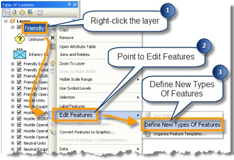
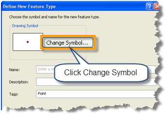
Next, you’d change the symbol for the new type of unit.
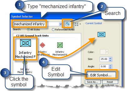
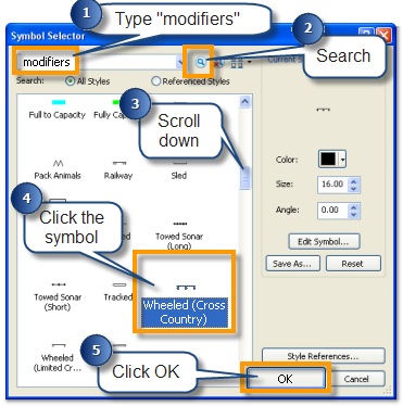
Next, you’d search for the right base symbol.
To show that the unit is wheeled, you’d add a symbol layer to represent that graphic modifier.
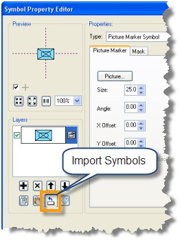
You’d search for the appropriate modifier in the Symbol Selector, much the same way you found the initial symbol.
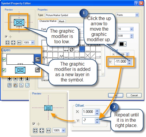
If necessary, you could use the controls on the Symbol Property Editor to adjust the placement of the new symbol layer.
For all UEI symbols there exists a base symbol in one of the styles which contains the frame and icon referenced by the Symbol ID code. Identity, Status, and symbol modifiers can be added to the symbol as additional layers to differentiate it. For most UEI symbols a feature template may not exist. In these cases the feature template needs to be added to the layer to which the symbol belongs.
Task Force, Headquarters, and Echelon graphic modifiers are examples of symbol layers that would frequently be added to a base symbol as part of defining a new UEI feature template. Unit symbols consist of a frame, a color, branch or functional symbols, and text or graphic symbol modifiers.
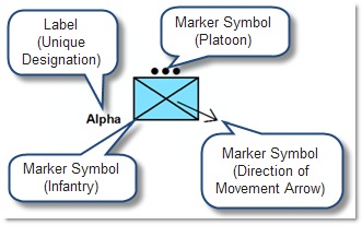
In the diagram below, the callouts indicate the required positions for the graphic components of Tactical Symbols (as defined by the 2525-C standard). Many other text modifiers exist as well, but they’ll be covered in another post.
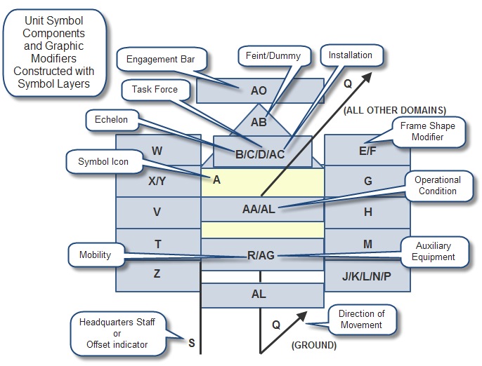
Unit symbol graphic components
|
Field |
Field Title |
Description |
|
A |
Symbol Icon | The innermost part of a symbol that represents a warfighting object. |
|
B |
Echelon | A graphic modifier in a unit symbol that identifies command level. |
|
D |
Task Force | A graphic modifier that identifies a unit or SO symbol as a task force. |
|
E |
Frame Shape Modifier | A graphic modifier that displays standard identity, battle dimension, or exercise amplifying descriptors of an object. |
|
Q |
Direction of Movement Indicator | A graphic modifier for units and equipment that identifies the direction of movement or intended movement of an object. |
|
R |
Mobility Indicator | A graphic modifier for equipment that depicts the mobility of an object. |
|
S |
Headquarters Staff Indicator/Offset Location Indicator | Headquarters staff indicator: A graphic modifier for units, equipment, and installations that identifies a unit as a headquarters. Or: Offset location indicator: A graphic modifier for units, equipment, and installations used when placing an object away from its actual location. |
|
AB |
Feint/Dummy Indicator | Feint or dummy indicator: A graphic modifier for units, equipment, and installations that identifies an offensive or defensive unit intended to draw the enemy’s attention away from the area of the main attack. |
|
AC |
Installation | Installation: A graphic modifier for units, equipment, and installations used to show that a particular symbol denotes an installation. |
|
AG |
Auxiliary Equipment Indicator | A graphic modifier for equipment that indicates the presence of a towed sonar array. |
|
AL |
Operational Condition | An optional graphic modifier for equipment or installations that indicates operational condition or capacity. |
|
AO |
Engagement Bar | A graphic amplifier placed immediately atop the symbol. May denote, 1) local/remote status; 2) engagement status; and 3) weapon type. |
The ArcGIS style files for Military Features contain symbols that combine the frame and color, as well as many branch or functional symbols. They also contain additional symbols for the various graphic modifiers. The text modifiers are added in a separate process, as they are labels based on individual feature attributes; the workflow for adding text modifiers will be covered in another post.
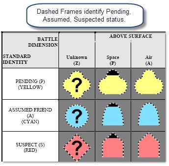
Status modifiers and amplifying descriptors
In Mil-STD-2525C terms, the status and details of a tactical symbol can be conveyed using various frame patterns or additional graphic elements. A dashed frame indicates Pending, Assumed, or Suspected status.
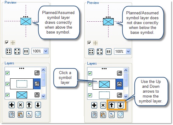
These graphic modifiers can be applied to UEI features by adding layers with corresponding marker symbols to the base symbol.
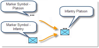
When adding symbols to a base, be aware that the symbols draw in order from the bottom to the top of the stack of symbol layers.
Exercise, Feint, and Dummy modifiers
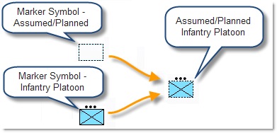
A symbol can be modified by adding a symbol layer to indicate that a given UEI Feature is part of an exercise.
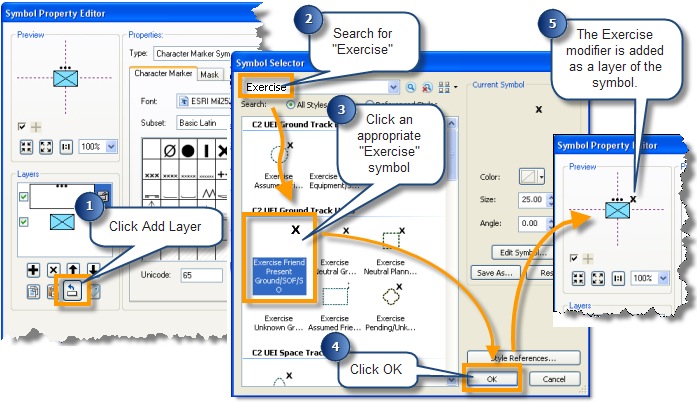
The same process would be used to indicate that a unit is a Feint, or that a piece of equipment is a Dummy. Add a new layer to the Unit symbol, and search for “Exercise.” Choose an appropriate exercise modifier and click OK.
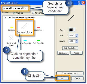
Operational condition modifiers
Equipment symbols can be given an Operational Condition modifier to indicate the status of the equipment. Add a new layer to the equipment symbol, and search for “operational condition.” Choose an appropriate condition modifier and click OK.
The military symbology styles contain the base symbols and graphic modifiers needed to create the symbols in the MILSTD-2525C standard. ArcGIS also comes other style files and fonts that can be used to construct additional symbols.
Content provided by Bob Booth.
Commenting is not enabled for this article.