By Charlie Frye, Esri Chief Cartographer
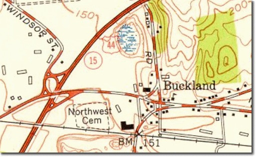
This is the first of three parts that cover how to symbolize roads with cased line symbols. This first part will cover how to symbolize road centerline data so that the symbols look good, the second part will cover data modeling and symbolizing underpass/overpass relationships, and the third part will deal with symbolizing cul-de-sacs versus dead-end streets. The primary inspiration for this task is the design of the USGS 1:24,000-scale topographic quadrangle maps. To the left is an example from the 1952 Manchester, New Hampshire map.
Two factors impact displaying road line data with cased symbols. First is the quality of the geometry used for road centerlines, and second are the settings for the symbols. We’ll cover some tips for improving or preparing your geometry to better support cased line symbols and the basic symbology options needed to display roads with cased line symbols.
Tips for creating high quality road line geometry:
- Manage the topology. All segments that are supposed to connect must connect at a single point. If you’re creating new data, the obvious trick is to use the Editor toolbar’s snapping environment to ensure that you connect lines properly while you’re editing. If you’ve got an existing road feature class, then you should create a geometric network (this requires an ArcEditor or ArcInfo license). The main advantage of doing this is being able to clearly identify where intersections exist. Junction points are created as part of the geometric network at all locations where endpoints are coincident. A secondary advantage is when you end a new road such that it connects somewhere in the middle of an existing road feature, that feature will automatically break to establish connectivity in all directions (to guarantee this behavior, ensure that you DO NOT create complex edges in your geometric network).
- Create smooth curves. Store your road line data in a geodatabase where you can edit features using curves, even if you have to share your data using the Shapefile format (shapefiles do not store true curve geometry, but you can always export your data to Shapefile format). In particular use the Endpoint Arc tool to create or reshape segments as curves that are smooth in appearance. The main advantage of using curves for features is that inadvertent zigzags and self intersecting line segments are avoided. Both of these problems occur fairly frequently when manually digitizing closely spaced points. A second advantage is that your data storage requirements will be smaller because the features will contain many fewer vertices.
- Manage digitized direction. There are at least three cases where a line feature’s digitized direction matters. To see where the start point is versus the end point, use the Editor and select a road, then change the Edit task to Modify Feature. This will show the end point of the line as a red vertex, and the rest of the vertices in green. Here are the cases that matter and why:
- One-way streets, restricted access highways, and on/off ramps. Why: these should be digitized only in the valid direction of travel. In a network dataset these will be flagged with an attribute that indicates that they are only valid in the digitized direction.
- Cul-de-sacs and dead-end streets. These should be digitized such that the start point connects to the other roads. Why: the end points should get flagged with an attribute that indicates what kind of symbol to show on the end point (this will be covered in part III).
- Address ranges. Normally, roads should be digitized starting with the lowest address number and ending with the highest address number. That makes
it easy to assign Left, Right, To, and From address range values. Why: these values support geocoding operations. The exceptions to this are the first two cases (i.e., one-way and dead-end streets), which may require that address ranges be flipped or reversed in order to support proper geocoding.
If a feature is oriented the wrong way, right click on the selected feature using the Edit tool and choose Flip to change its direction.
Symbolizing roads with cased lines
Cased line symbols are accomplished by using at least a two-layer line symbol. The first, bottommost, layer is a wide line, typically black. The second is a slightly narrower line that is colored. An optional third, topmost layer might include a dashed line which might look like the red and white line above, or a thin dark centerline to indicate a divided highway. An example of the two-layer symbol is the Freeway line symbol in the Esri.style file (ArcMap’s default style). This symbol also shows the correct properties for the line caps (Butt) and joins (Round). If you’re creating your own line symbols, be sure to set the cap and join properties as shown here:
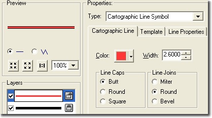
The line caps determine how the ends of line feature meet one another. Most mapping conventions leave them open, or close them with an end that represents how the feature works on the ground, e.g., a cul-de-sac. The joins determine what happens at vertices within lines.
There are two steps that contribute to high quality depictions of roads with cased line symbols.
- Dissolve by road name and symbol. In the image on the left (below), notice the breaks in the casements of the curved street. These breaks occur because there are multiple features comprising the curve and the butt-end of the symbol is perpendicular to the first and the last segment of each feature, which are at slightly different angles and therefore show a gap. To correct this, use the Dissolve tool, specifying the name field and field you will use for determining which symbol each road will be shown with as the dissolve fields; and make sure the option to produce multi-part shapes is unchecked. The result is shown below to the right.
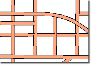

- Symbol Level Drawing: In both of the images above, notice how two of the casings always intrude on the intersection. This is because the features are being drawn in the order they are read from the database (this could be random or in the order they appear in the attribute table). To fix this, use the Advanced button on the Symbology Tab of the Layer Properties dialog box and choose Symbol levels. Check the option to use Symbols levels and set the properties needed to layer the symbols. The image below shows the result:

While the link to the Symbol Levels help topic will get you started, the next part of this series will provide an in-depth example of how to handle symbol levels for multiple types of roads and for underpass and overpass relationships.
Note: In the images above the depiction of the line casings look “ratty”. This is because the casings are very narrow (effectively 0.4 points) which is very hard to represent cleanly on a computer screen. These will look fine when printed. The cased line symbols in the Esri style were designed with this problem in mind and use the minimum widths to permit both sides of the casings to show in on-screen maps without having to resort to setting a reference scale.


Article Discussion: