By Aileen Buckley, Mapping Center Lead
Sun glints are a way to add a more realistic effect to your map by modulating the tone of water features. We rarely see flat tones in nature, so using sun glints simulates the subtle tonal variations caused by the reflection of sunlight off a water surface. This method was first described in Tom Patterson’s article, “Getting Real: Reflecting on the New Look of National Park Service Maps” on his Shaded Relief web site. Although he describes how he achieved the effect using Photoshop, this tip describes how you can use ArcMap to accomplish the same thing.
The example used a map of the southwestern part of Oregon in the Crater Lake area (figure 1).
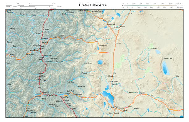
Figure 1. Crater Lake area map
In essence, sun glints are symbolized using a gradient fill for the water polygons (figure 2). The angle of the gradient fill varies randomly from feature to feature.
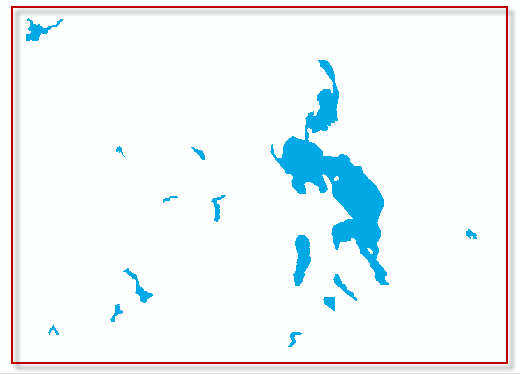
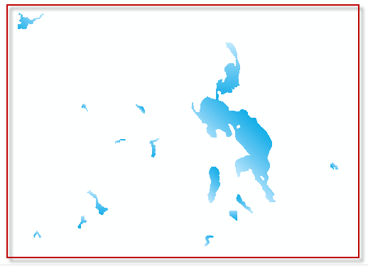
Figure 2. Water polygon features symbolized without sun glints (left) and with sun glints (right).
To achieve this effect, you only need a water polygon feature class.
Step One
Using a random number calculation, you can add an attribute that distinguishes which features will be symbolized with gradient fills from varying angles. To do that, for the layer that contains the water features, open the attribute table, add a new field, and calculate it to contain random numbers:
- Right click the water polygons layer in the table of contents and open the attribute table.
- At the top left of the Table dialog box, click the Table Options button and click Add Field.
- Name the field and keep it a short integer type.
- Click OK.
- Right click the name of the field and click Field Calculator.
- Choose the option to use the Python parser.
- Also choose the Show Codebook option.
- In the Pre-Logic Script Code area type the code as shown in the figure below. Note that the following expression calculates random values from 1 to 4—you can modify these values if you want but realize that you will need to define a new symbol for each random number.
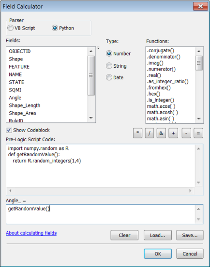
- Type the following at the bottom, under where your new field name is shown: getRandomValue()
- If desired, click the Save button to save the expression so you can use or modify it later.
- Click OK.
- Verify that the field now contains random numbers for the range you defined.
- Close the attribute table.
Step Two
The next step is to symbolize the features:
- Right click the layer in the table of contents and click Properties.
- Click the Symbology tab, and choose to use the Categories > Unique values renderer.
- Set the value field to the attribute you added in step one.
- Click Add All Values.
- Right click any symbol and click Properties for All Symbols.
- On the Symbol Selector dialog box, click Edit Symbol.
- On the Symbol Property Editor dialog box, change Type to Gradient Fill Symbol.
- Right-click the color ramp Style and click Properties.
- Click the Color 2 option to enable the second color.
- Click the Color 2 color patch to change the color.
- Select a light blue color or click More Colors to define your own color (this example used RGB 191 233, 255).
- Click the Color 1 color patch to change the color.
- Select a darker blue color or click More Colors to define your own color (this example used RGB 0, 168, 230).
- Click OK on the Edit Color Ramp dialog.
- On the Symbol Property Editor dialog, right-click the modified color ramp and click Save to Style.
- Give it a name so that you will recognize it when you see it in your personal style.
- Change Intervals to 50, Percentage to 100, and Angle to 135 (figure 3). What this does is adds a smoother appearance to the color gradation by using more intervals, applies the gradient fill across 100 percent of the polygon features, and changes the angle of the gradient fill from E (90) to SE (135).
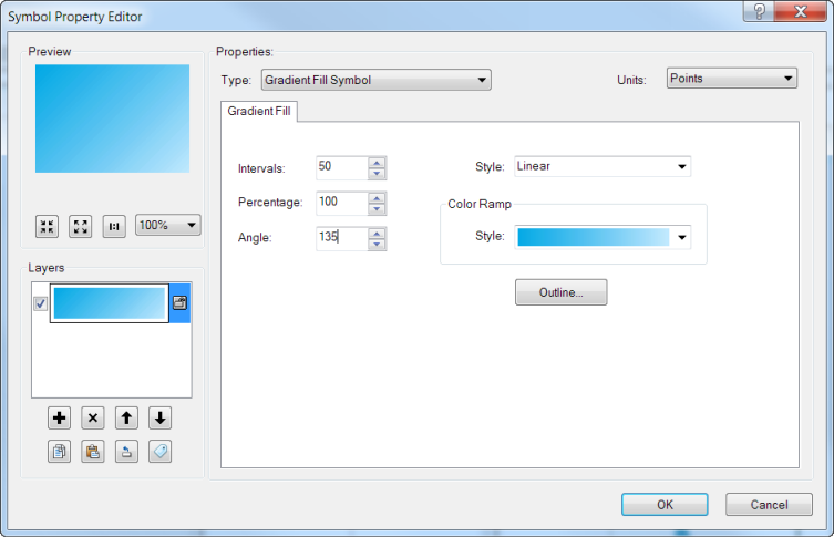
Figure 3. Symbol Property Editor - Click OK.
- On the Symbol Selector dialog box, change Outline Color to No Color.
- Click OK.
- Click Apply to see your changes so far.
Step Three
The final step is to modify the symbols so the features with different attribute values have gradient fills with different angles.
- Decide which symbol will retain the symbology definition you just set.
- Right-click one of the other symbols, click Properties for Selected Symbol(s), then click Edit Symbol.
- Change Angle to 45, click OK, and click OK.
- Repeat steps 2 and 3 above for the other symbols using other angles (for example, 225 and 315).
- Verify that the symbols appear different for each value (figure 4).
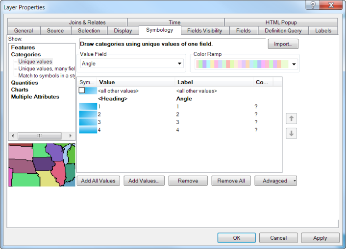
Figure 4. Layer Properties dialog box
- Click OK to save your changes.
The results, when combined with other methods that promote a feeling of realism on a map, such as hillshading and elevation tinting, provide a much more aesthetically pleasing impression (figure 5).
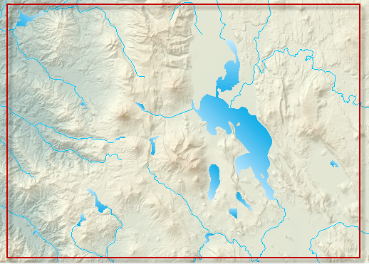
Figure 5. The sun glints with other “realistic” symbology such as hillshades and elevation tints
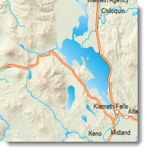
On the final map, the sun glints add a subtle professional touch (figure 6).
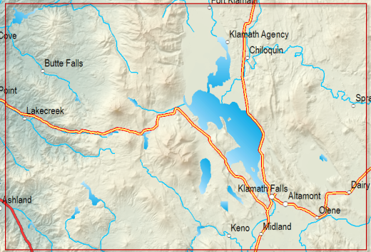
Figure 6. The sun glints on the final map
Thanks to David Barnes, Cartographic Product Engineer, for his Crater Lake area map.

Article Discussion: